
Bracket Challenge
Sand Casting | CNC Machining | Heat Treatment
A design challenge to support 400lbs of cantilevered weight using <0.2lbs of cast aluminum.
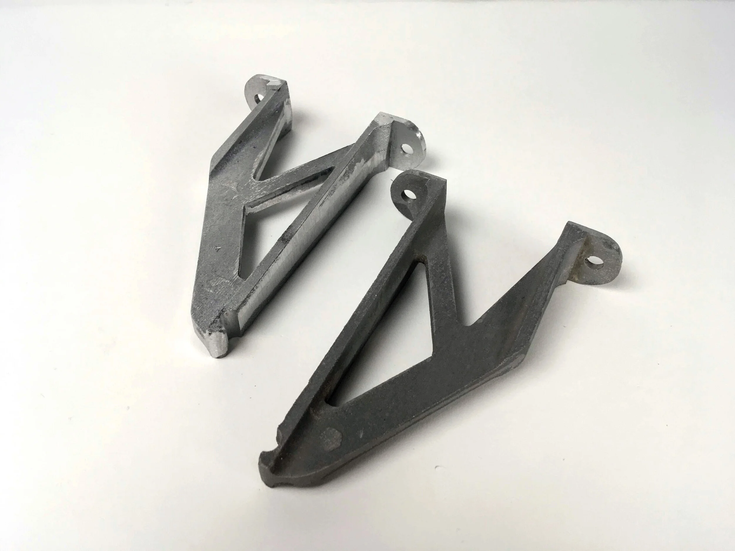
The final brackets. The brighter left-hand bracket is untreated while darker right-hand bracket received a T6 precipitation heat treatment.
Materials.
| Aluminum 356
| UHMW
Processes.
| CAD modeling (Solidworks)
| Topology Optimization (Solidworks)
| CAM programming (HSM Works)
| CNC milling (Haas VF2, ShopBot)
| Pattern making
| Sand casting
| Manual milling
| Heat Treatment
Timeline.
| 3 weeks
Context.
As part of a 2-person team for the class “ME 365: Making Multiples: Sand Casting,” Elliot Helms and I designed this bracket for a strength to weight ratio challenge. The design prompt required that a cantilevered aluminum bracket weighing less than 0.2lbs support a 100lbs weight at a 5” distance from a mounting plate.
Design.
We started simple, with an I-beam design that maximized area moment of inertia. From there we used topology optimization to take a rough beam shape and create a geometry that had excellent strength to weight ratio and adhered to design constraints. We used a Design Study in Solidworks to compare 12 different rib geometries for maximize strength and stiffness with our given mass.
Manufacturing.
We CNC milled the pattern out of TIVAR® 1000 UHMW using a printed sticker, acrylic sheet, and brass screws for unobtrusive fixturing. Then I hand built the pattern-board using plywood, dowel pins, and shellac. After pouring the parts, we picked the two highest quality castings, manually post-machined them, and then applied a T6 precipitation heat treatment to one of the castings.
Outcome.
On test day, both the heat treated and the untreated brackets were able to support 400lbs without failure, the highest weight available for testing. This was unsurprising, as our FEA analysis showed a FOS of 5.

Holding a recently poured aluminum casting.

A progression of topology optimizations in Solidworks. We used this design tool to maximize the stength/weight ratio of our bracket while reducing the weight to less than 0.2lbs. Afterwards we used the Design Study tools in Solidworks to refine the rib thicknesses to further maximize strength/weight ratio on the rightmost design.

FEA in Solidworks showing a factor of safety of 5 for the yield strength of our bracket after a T6 heat treatment.

Maximum deflection of the bracket with 100lbs was expected to be around 2mm.
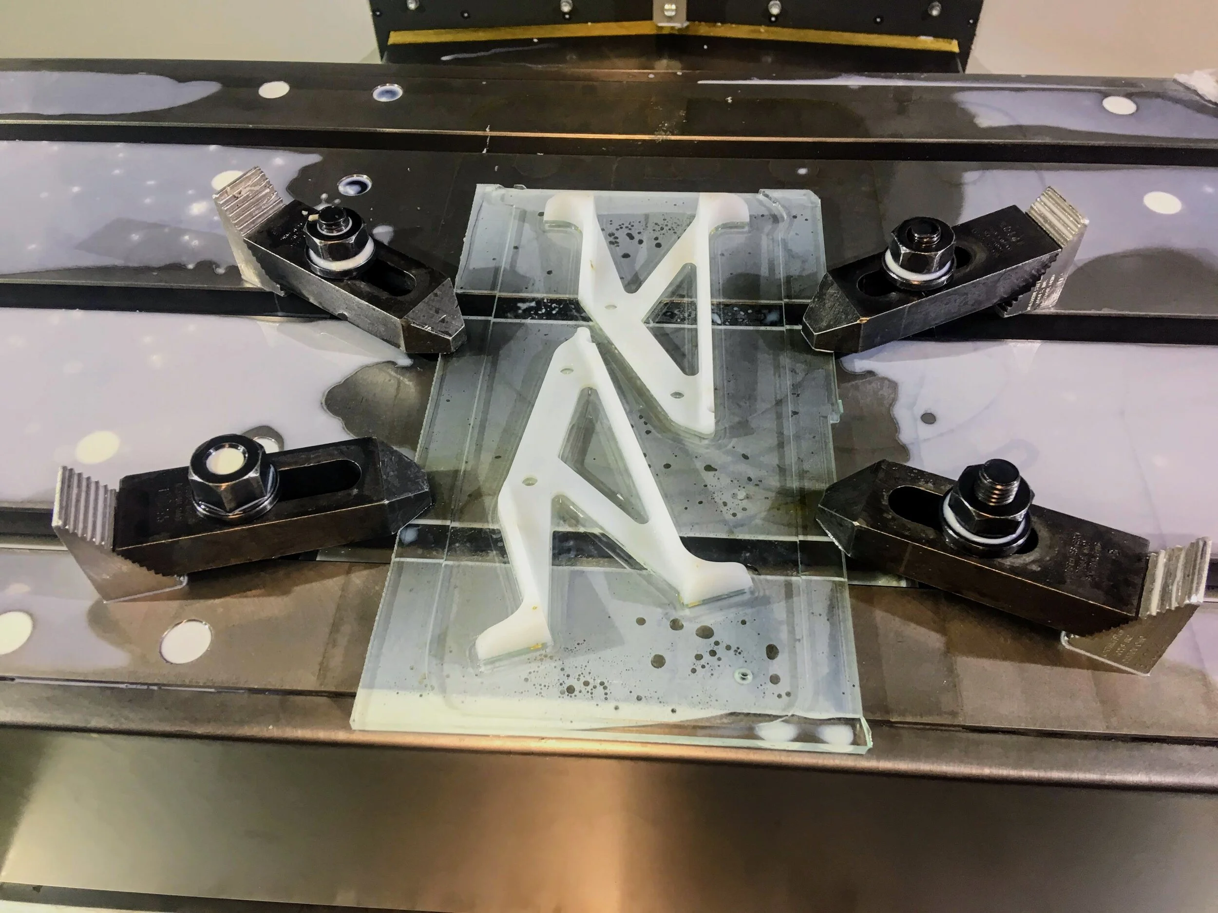
CNC machining the pattern out of UHMW. Fixturing accomplished with brass screws holding the stock to an acrylic plate.
The two-sided pattern affixed to the pattern-board with dowel pins for alignment (before applying shellac).

The finished pattern-board with shellac. The drag side of the pattern with gate and runner is visible.

Finished sand mold with pattern in the foundry.

Close up of a clean pull of the pattern out of the sand.

Aluminum castings. Some parts suffered from misalignment due to the hand-work nature of our foundry.

Tools, soft jaws, and engineering drawing for manual machining.

Manual machining the cast brackets in order to remove parting line and draft for flat mounting.

Quenching the bracket during the heat treatment process.

Testing our bracket with ingots as weight.
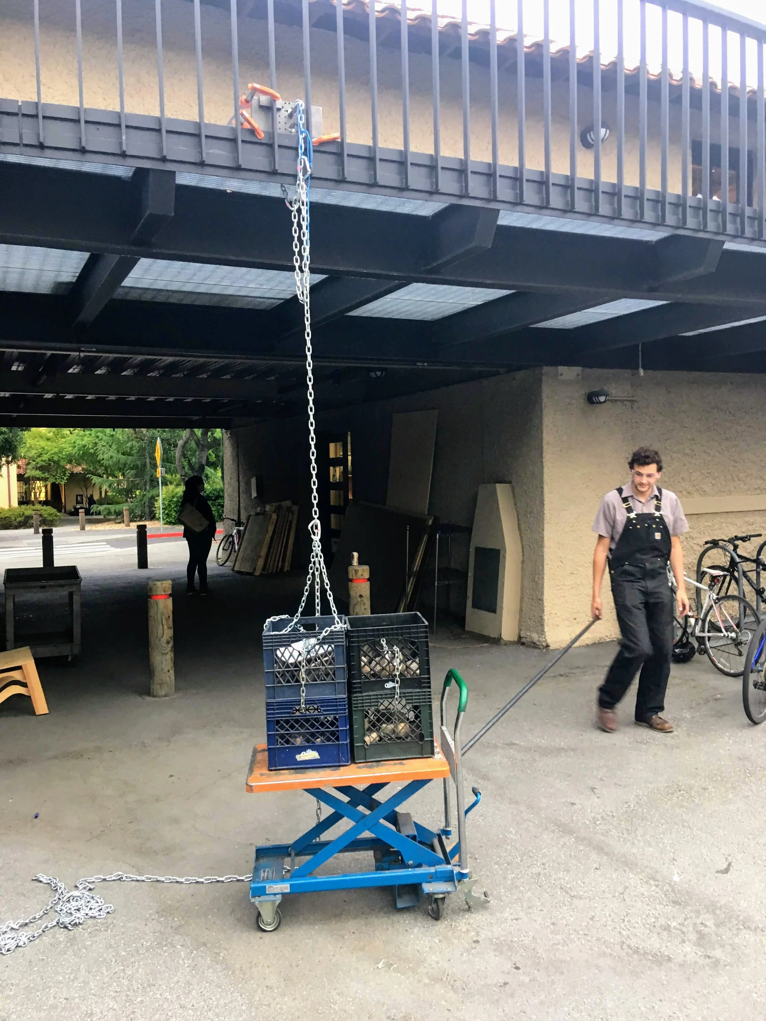
Testing was done in the PRL courtyard.

Other bracket designs lined up on test day.

Me holding a recently cast bracket.