Prototype Mechanical Systems
Mechanism Design | Efficiency Analysis
Two mechanical system design challenges involving self-actuated mechanisms and DC motor systems.
Context: For both projects, I worked on a four-person team as part of the ME 112: Mechanical System Design class at Stanford. All team members participated in all aspects of the project, but I was primarily responsible for mechanism design in both projects.
Crawler
Components.
| 5V brushed DC Motor
| Laser cut parts
| Lego bricks and gears
Design.
| Bi-stable mechanism
| 4-wheel drive-train with 75:1 transmission
Timeline.
| Two weeks
Challenge.
Design a mechanical, autonomous system capable of traversing a narrow, 2-meter-long tunnel filled with gravel and retrieve a plastic salamander using as a little energy as possible. Ultimately, my team’s crawler traveled at an average speed of 0.201 meters per second and consumed 3.95 Joules of energy to complete the salamander retrieval task in testing. Our crawler had a motor efficiency of 36%, a transmission efficiency of 52%, and an overall system efficiency of 15%.

Iterative wheel designs.

Late-stage prototype with four-wheel drive and alternate grabbing mechanism.

Mid-stage prototype with functioning rear-wheel drive-train and salamander grabbing mechanism.

Crawler robot retreating down the tunnel with captured salamander.

Early prototype.
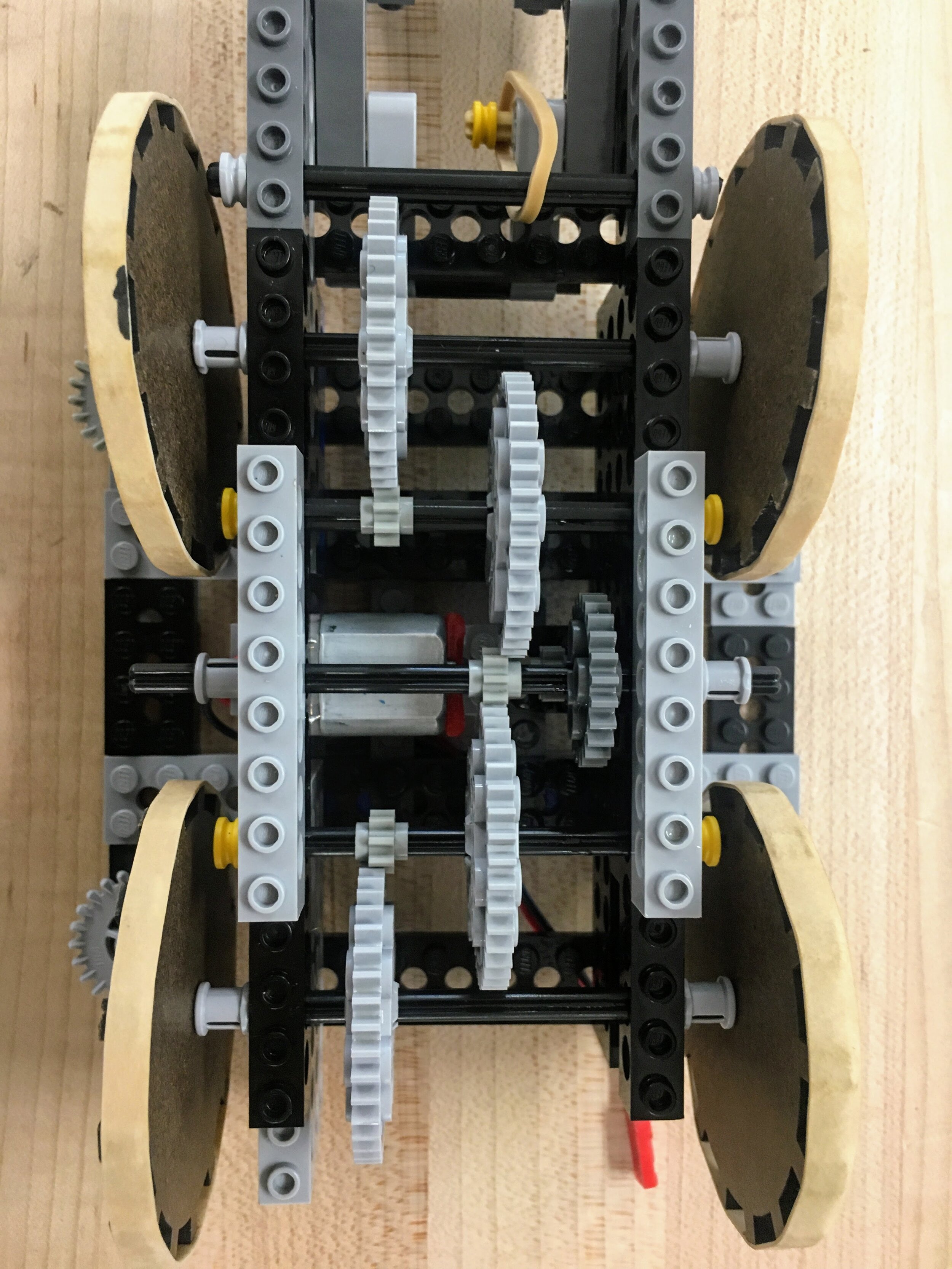
Top-down view of our 70:1 four-wheel drive lego transmission.

Top-down view showing how four linear guide-wheels directed our robot down the tunnel.
Bi-stable Mechanism Design.
At the end of the tunnel, the crawler needed to grab a plastic salamander without any external input or electric sensing. I designed, prototyped, and refined a bi-stable mechanism that was powered by a rubber band, was activated by the wall at the end of the tunnel, and proved 100% reliable for grabbing the salamander. Most project teams utilized unreliable adhesives to try and grab the salamander.
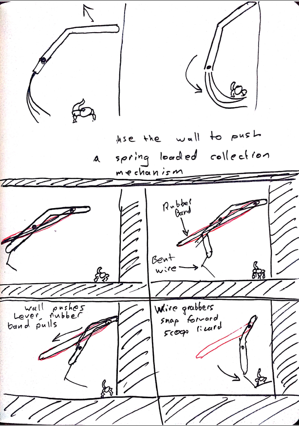
Early sketches

First mechanism prototype.

Second mechanism prototype.

Late stage prototype in unfired position.
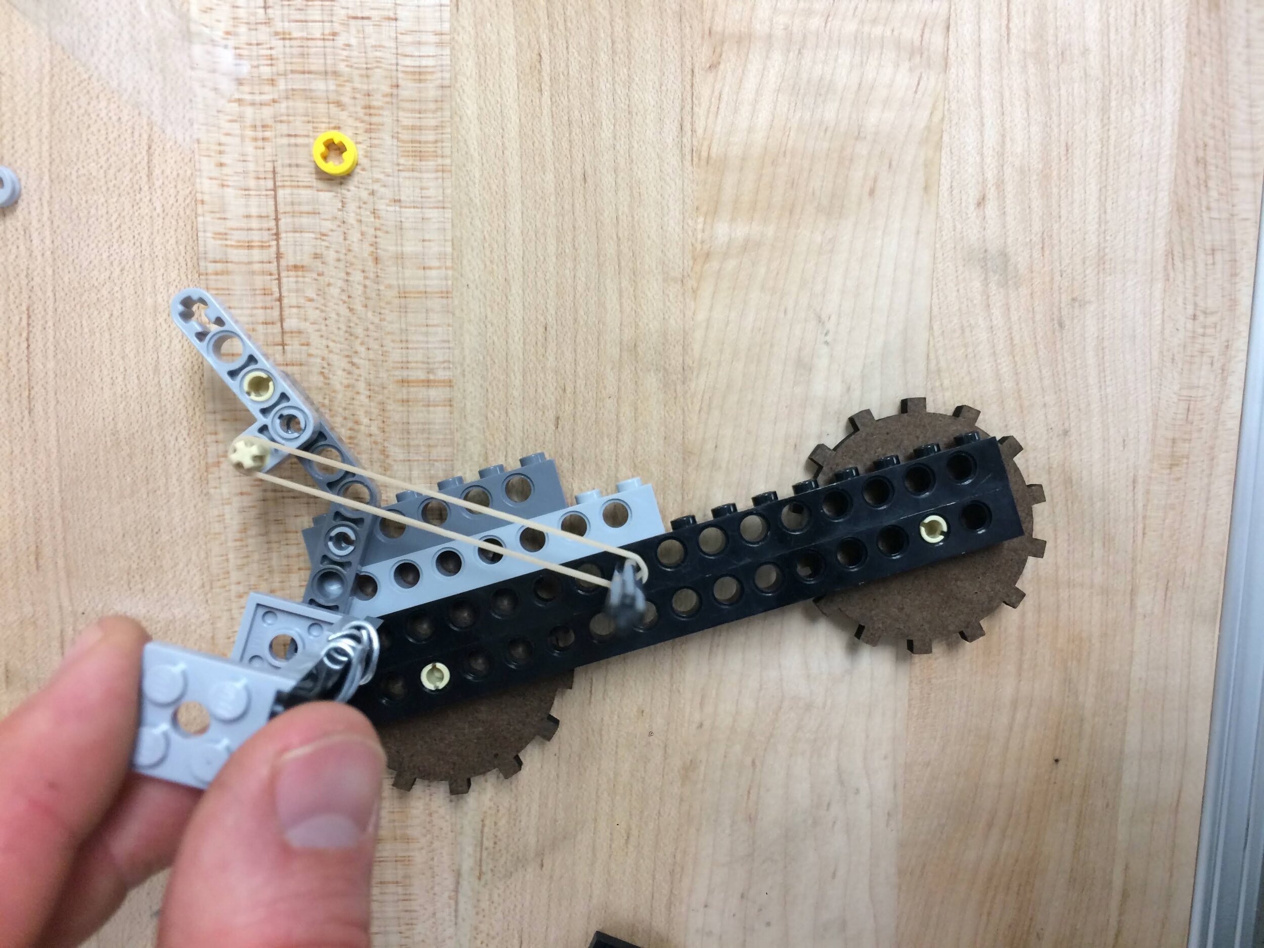
Late stage prototype in fired position.
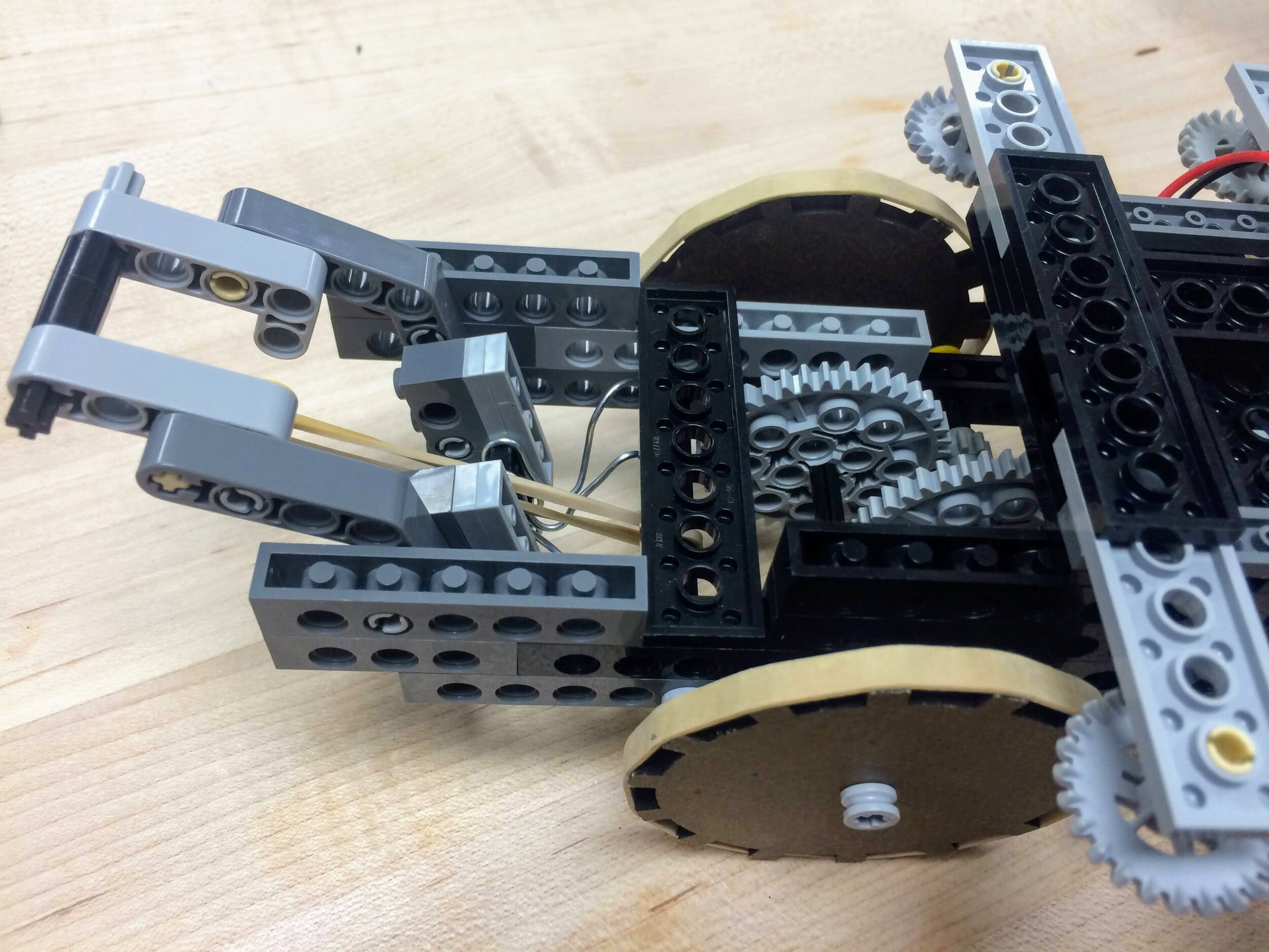
Closeup of final mechanism in the unfired position.

Top down view of final mechanism in unfired position.
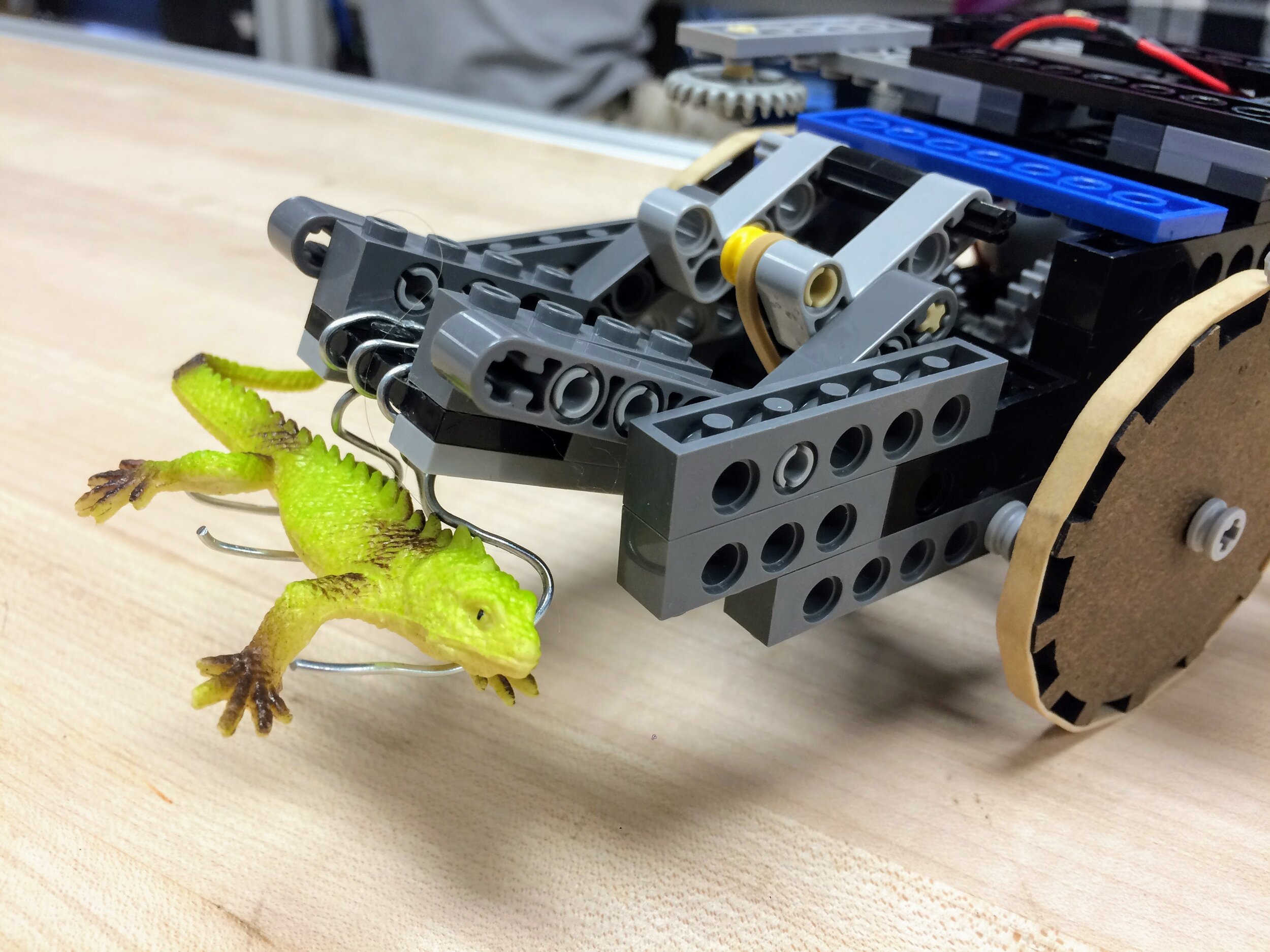
Closeup of mechanism holding salamander.

Left: Unfired mechanism before contacting the wall. Right: Fired mechanism holding the salamander after contacting the wall.

